THE USE OF FREQUENCY CONVERTERS IN THE ELECTRIC DRIVE OF THE COOLING PUMP OF THE MAIN DIESEL ENGINE OF THE VESSEL
Журнал: Научный журнал «Студенческий форум» выпуск №43(179)
Рубрика: Технические науки

Научный журнал «Студенческий форум» выпуск №43(179)
THE USE OF FREQUENCY CONVERTERS IN THE ELECTRIC DRIVE OF THE COOLING PUMP OF THE MAIN DIESEL ENGINE OF THE VESSEL
One of the most important areas of automation in the fleet includes automated control systems for ship power plants (ACS SEU), which combine control systems for the main and auxiliary mechanisms of the vessel. One of these systems is the cooling system of the main diesel engine using fresh water.
Improving the process of regulating the speed of the electric motor of the main diesel cooling system is one of the developing areas of ship automation. Technologically, this is expressed in the gradual displacement of mechanical regulators by electronic systems that carry out the control process using signals generated by sensors responsible for the state of fresh water used to cool the main engine.
If the engine is not cooled, then its operation is impossible, which will cause it to break down. Engine lubrication will also become impossible, as the lubricating oil will burn. To exclude this, all parts and components of the engine in contact with hot gases must be cooled. Cylinders, cylinder covers and exhaust manifold are subject to mandatory cooling [9].
The wear of parts of the cylinder-piston group of engines is significantly affected by the temperature regime in the cooling system [8]. When the temperature of the cooling water decreases, chemical corrosion increases, caused by the action of sulfuric acid condensing on the walls of the cylinder, which increases its wear.
The temperature regime has a serious impact when burning sulfur fuels in engines [7]. The intensity of sediment formation in the crankcase of the engine depends on the temperature of the oil and cooling water. With a decrease in temperatures, the intensity of sediment formation increases, i.e. the condensation of acidic combustion products of fuel and water flowing down with unburned fuel and oil along the cylinder walls into the crankcase increases, and this already negatively affects the condition of the engine.
The standard electric drive of the main diesel cooling pump is a classic magnetic starter circuit, shown in Figure 1. The engine of the AIR system is installed in it.
The systems were analyzed on the basis of mechanical, dynamic and transient characteristics.
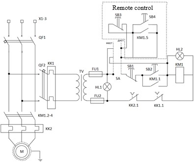
Figure 1. Schematic electrical diagram
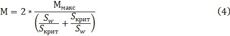
The construction of the mechanical characteristic from S=0 to Scrit is carried out according to the Kloss formula (4) and the accompanying formulas for calculation (1), (2), (3) [7, p. 19]:
![]()
![]()

where ![]() - the rated motor speed, rad/min;
- the rated motor speed, rad/min;
![]() - the synchronous motor speed, rad/min;
- the synchronous motor speed, rad/min;
![]() – nominal slip for the engine;
– nominal slip for the engine;
![]() - coefficient showing the ratio
- coefficient showing the ratio ![]() /
/![]() = 2.9;
= 2.9;
![]() – maximum engine torque, N*m;
– maximum engine torque, N*m;
![]() – rated motor torque, N*m;
– rated motor torque, N*m;
![]() - critical slip;
- critical slip;
![]() - sliding at w rad/min;
- sliding at w rad/min;
M - the moment at w rad/min, N*m.
The construction of the mechanical characteristic from ![]() to S = 1 is carried out according to formulas (5) and (6) [7, p. 20]:
to S = 1 is carried out according to formulas (5) and (6) [7, p. 20]:
![]()

where ![]() - a coefficient showing the ratio of
- a coefficient showing the ratio of ![]() /
/![]() ;
;
![]() – starting torque of the engine, N*m;
– starting torque of the engine, N*m;
The mechanical characteristics of the initial AIR engine and the new ADHR engine are shown in Figure 3.
The construction of the electromechanical characteristics of the initial AIR engine and the new ADHR engine is carried out according to formulas (7) and (8) and is shown in Figure 4 [7, p. 20]:
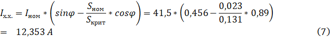

where ![]() - the rated current of the motor = 41.5 A;
- the rated current of the motor = 41.5 A;
![]() - the idling current of the engine, And;
- the idling current of the engine, And;
![]() - engine torque for w rad/min, N*m;
- engine torque for w rad/min, N*m;
![]() - correction factor = 1.3;
- correction factor = 1.3;
![]() - the current at w rad/min, A. The
- the current at w rad/min, A. The
Construction of the mechanical characteristics of the load was carried out according to the formula (9) and is shown in Figure 2:
![]() (9)
(9)
where ![]() N*m is the pump torque;
N*m is the pump torque;
![]() N*m is the load moment at idle;
N*m is the load moment at idle;
![]() - synchronous speed for this pump = 314.13 rad/min;
- synchronous speed for this pump = 314.13 rad/min;
![]() – pump power, W;
– pump power, W;
![]() – nominal speed of rotation of the pump;
– nominal speed of rotation of the pump;
![]() – actual speed, rad/min.
– actual speed, rad/min.
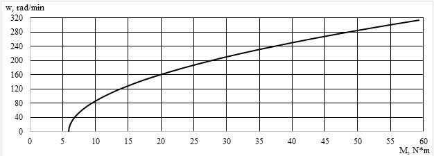
Figure 2. Load characteristic of the pump
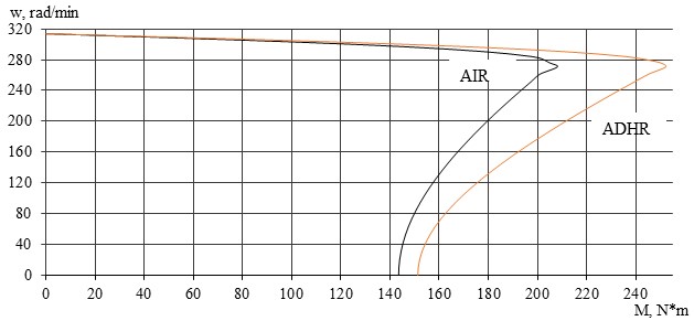
Figure 3. Mechanical characteristics of the initial and new engine

Figure 4. Electromechanical characteristics of the initial and new engine
To plot transients, it is necessary: 1) calculate the dynamic moment of the initial motor and build a dynamic characteristic, 2) divide the mechanical characteristic of the initial motor of the electric drive into intervals Δw, 3) calculate in these intervals ![]() and 4) calculate the time ∆t for which the motor accelerates by Δwn, the current changes by ΔIn or the moment changes by ΔMn.
and 4) calculate the time ∆t for which the motor accelerates by Δwn, the current changes by ΔIn or the moment changes by ΔMn.
The calculation of the dynamic moment is carried out according to the formula (10) [7, p. 23]:
![]()
where ![]() - the load moment, N*m;
- the load moment, N*m;
M - the engine torque at w rad/min, N*m;
![]() - dynamic moment, N*m.
- dynamic moment, N*m.
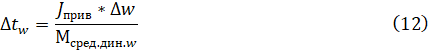
The transient characteristics of the initial engine are calculated according to formulas (11) and (12) [7, p. 23]:
![]()
where ![]() - the dynamic moment for the nth segment, N*m;
- the dynamic moment for the nth segment, N*m;
![]() - dynamic moment for n+1 segment, N*m;
- dynamic moment for n+1 segment, N*m;
![]() - reduced moment of inertia≈0.385 N*m^2;
- reduced moment of inertia≈0.385 N*m^2;
∆w – speed section ![]() , rad/min;
, rad/min;
![]() - the time during which the speed changes by ∆w, s.
- the time during which the speed changes by ∆w, s.
When performing calculations and analyzing the system, the main drawback was revealed - the inability to regulate the speed of the pump's electric motor, as a result of which the engine after starting, regardless of the heating of the ship's main diesel engine, always operates at nominal speeds.
Another disadvantage of a standard electric drive is the lack of energy saving, and this is one of the main trends in modern energy and economics.
To correct the shortcomings of this system, it is necessary to modernize the control system of the electric drive in order to be able to adjust the operating mode of the engine depending on the needs of the technological process (i.e., from the heating of the engine). This can be achieved by introducing a frequency converter into this system.
Adjustment of the control action on the engine will be carried out through negative feedback on the current from the temperature sensor, which will need to be installed at the outlet of the ship's engine, namely on the section of the pipeline exiting the engine (the sensing element will be installed inside the pipeline, and the rest in a special pocket). Additionally, thanks to the adjustment of the engine operating mode, the accompanying positive effect will be energy savings, since the engine will not always be loaded to its nominal characteristics and wear of the mechanical parts of the engine and pump will decrease.
We have developed an electrical schematic diagram of the upgraded system, shown in Figure 5 (A2 is a measuring converter of the temperature of the water used to cool the engine, A1 is an IF). In addition, the engine was replaced with a similar engine in terms of characteristics, but of the ADCR brand, for better interaction with the frequency converter, because when working with an IF, the engine rotation speed will be lower than the nominal one, which means cooling will deteriorate, therefore an engine with insulation of a higher class of heat resistance and a forced ventilation system is needed. This is exactly what the engine of the ADHR system provides.
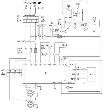
Figure 5. Electrical schematic diagram
In the IF, a control program was prescribed in which, at f = 50 Hz, the Мпуск=1,5Мном of the new engine. The following characteristics are set by the ratio ![]() . The characteristic of the engine when working with an IF is programmed so that at the beginning of the M of the engine increases to the moment of the engine equal to Mn, and then supports it. The change in the value of the supplied voltage and its frequency is carried out depending on the temperature of the working fluid, i.e. the lower the temperature of the working fluid, the lower the rotation speed of the electric motor and vice versa.
. The characteristic of the engine when working with an IF is programmed so that at the beginning of the M of the engine increases to the moment of the engine equal to Mn, and then supports it. The change in the value of the supplied voltage and its frequency is carried out depending on the temperature of the working fluid, i.e. the lower the temperature of the working fluid, the lower the rotation speed of the electric motor and vice versa.
Calculation and construction of the mechanical properties is carried out according to the formula Kloss (4) and related to the calculation formulas (1), (2), (3), (5), (6) and Electromechanical characteristics is carried out according to the formulas (7) and (8).
The mechanical characteristics of the engine without the drive and the drive at different speeds and at start-up is depicted in figure 6.
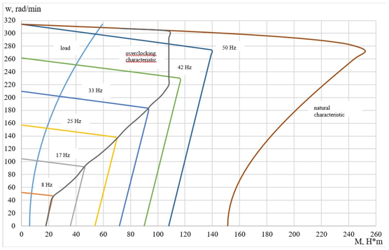
Figure 6. Mechanical characteristics of the engine without IF and with IF
The electromechanical characteristics of an engine without an IF and with an IF at different speeds and at start-up are shown in Figure 7.
![]()
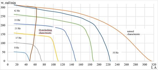
Figure 7. Electromechanical characteristics of the engine without IF and with IF
The transient characteristics of the ADCR180S2 engine with a frequency converter are calculated according to formulas (11) and (12). The transition process is considered for the acceleration characteristic.
Transitional characteristics for systems before and after modernization are shown in Figures 8-10.
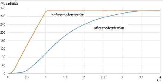
Figure 8. Speed transients before and after modernization
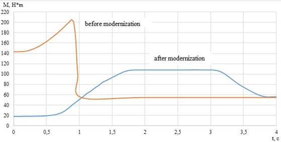
Figure 9. Transients by the moment before and after modernization
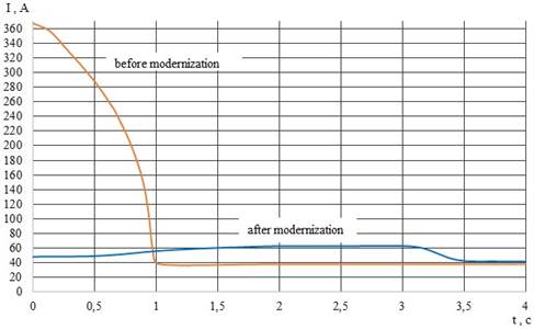
Figure 10. Current transients before and after modernization
Thanks to these upgrades, the main problem of the existing system was solved, i.e. in the upgraded system, a program was implemented that regulates the speed of rotation of the engine depending on the temperature of the working fluid. Also, due to the fact that the engine will not always operate in nominal mode, it will consume less electricity, which will lead to additional energy savings and reduce wear on the mechanical parts of the engine and pump. Also positive factors are an 8-fold reduction in starting torque (from 143.3 Nm to 17.94 Nm), a 5.87-fold reduction in starting current (from 282 A to 48 A) and a smoother engine start (1 second before modernization and 3.76 seconds after modernization).
