STRUCTURAL DESIGN SOLUTIONS FOR DRAINAGE SYSTEMS OF TRANSPORT INFRASTRUCTURE IN FLOOD-PRONE AREAS
Журнал: Научный журнал «Студенческий форум» выпуск №16(367)
Рубрика: Технические науки

Научный журнал «Студенческий форум» выпуск №16(367)
STRUCTURAL DESIGN SOLUTIONS FOR DRAINAGE SYSTEMS OF TRANSPORT INFRASTRUCTURE IN FLOOD-PRONE AREAS
At present, due to global climate change, human life is becoming more difficult. Climate change may create unfavorable conditions for agriculture, crops, and the economy [1].
If we compare the consequences of global climate change between 1991–2020 and 1961–1990, the temperature has increased by 0.9°C. This climate change has a strong impact on life, especially posing risks of negative effects on transport structures and transportation systems.
A significant part of transport infrastructure in Kazakhstan was built in the 19th century. Currently, the drainage structures of transport facilities are outdated and do not meet modern requirements. Therefore, considering current climatic conditions, it is necessary to review them in accordance with modern standards [2].
It is necessary to increase the water discharge capacity of transport structures, and during reconstruction, taking into account the road slope, to improve the quality of areas where floods occur through engineering solutions and expand drainage structures in accordance with modern standards.
Due to the significant increase in logistics cargo transportation, the growth of traffic intensity and the increase of loads on road structures, the design of engineering structures under current conditions considers the use of generalized effective constructions from various materials, which leads to an extension of the service life of roads [3].
As an example, the embankment and cutting cross-sections of a railway are considered. The railway embankment section is divided into an upper and a lower layer. The upper layer consists of rails, rail fastenings, sleepers, ballast layer, and the formation level. The lower layer consists of the subgrade and structures [4]. The structural design of the formation has a trapezoidal shape with a top width of 2.3 m and a height of 0.15 m for single-track lines [6]. For double-track lines, it has an isosceles triangular shape with a height of 0.2 m. Figure 1 shows a typical embankment (a) and a cross-sectional scheme (b).
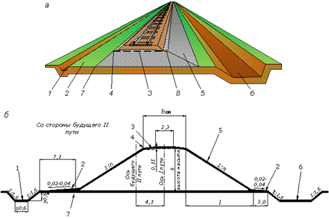
Figure 1. General view of the embankment structure (a) and its cross-sectional layout (b).
1 – drainage ditch; 2 – subgrade berm; 3 – formation level (upper layer); 4 – edge of the subgrade; 5 – subgrade slope; 6 – borrow pit (reserve); 7 – base of the embankment; 8 – edge of the subgrade; 1:n – slope ratio of the embankment.
Surface water drainage from embankments constructed from imported soil is carried out by longitudinal drainage ditches [5]. The width (at the bottom) and depth of these ditches must be at least 0.6 m. When the transverse slope of the terrain is up to 0.04‰, ditches are arranged on both sides, and when the slope is higher, only on the uphill side. If the embankment is constructed using local soil, excavated depressions formed during construction are used for drainage, which are called reserves (borrow pits). A longitudinal slope of at least 0.002‰ is provided at the bottom of reserves and drainage ditches [7].
The strip of land located between the toe of the embankment slope and the drainage ditch or borrow pit is referred to as a berm. To ensure efficient surface water runoff from the embankment, the berm is designed with a gradient of 0.02–0.04‰ directed toward the drainage system.
The cutting (excavation) and its typical cross-section are shown in Figure 2 (a, b) [6]. The dimensions of the formation in the cutting are similar to those in the embankment. In the cutting, longitudinal drainage channels are arranged on both sides of the formation, which are called side ditches (cuvettes). The depth of the cuvettes is usually 0.6 m, and the bottom width is at least 0.4 m. A longitudinal slope of 0.002 is provided at the bottom of the cuvettes.
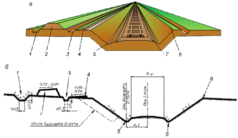
Figure 2. Cutting (a) and its typical cross-section (b) (dimensions are given in meters):
1 – drainage ditch on the uphill side; 2 – cavalier; 3 – ditch outside the berm; 4 – berm; 5 – cuvette; 6 – slope edge; 7 – road edge.
The removal of surface water ensuring the stability and preservation of the subgrade of railways and highways must be carried out from embankments through longitudinal ditches or reserves, from cuttings through uphill (nagorny) and post-berm ditches, from zero-cut sections through cuvettes and channels, as well as from the carriageway and median strip of highways through channels [6].
When the transverse slope of the terrain is less than 0.02, when the embankment height is less than 2 m, in sections with variable transverse slope direction, as well as in marshy areas, longitudinal drainage ditches or reserves are designed on both sides of the embankment.
When the transverse slope of the terrain is pronounced, that is, when water reaches the subgrade only from the upper (uphill) side, ditches or reserves should be provided only on the uphill side [7].
When the slope of surface water flowing from adjacent hillsides to the subgrade is significant, the placement of two or more levels of uphill ditches is permitted.
In water-saturated and excessively moistened soils that cannot maintain slopes (as well as in confined conditions and in settlements), when organizing drainage facilities, longitudinal channels may be used which, when necessary, ensure the drainage of the subgrade and the passage of the design water discharge [8].
Water from ditches, cuvettes and channels may be discharged to lower-lying areas of the terrain, provided that this does not lead to waterlogging of the area and accumulation of water near the subgrade.
From the specified water receivers, it shall be ensured that water flows by gravity away from the subgrade in the opposite direction or, if necessary, is diverted through ditches and outlets to nearby properly reinforced artificial structures. When approaching the water receivers, ditches should be widened with a flattening of their slopes.
Water from ditches, reserves and cuvettes may be discharged onto the slopes of gullies, provided there is no risk of gully formation. The slopes of gullies at discharge points shall, if necessary, be protected against erosion [9].
Water from cuvettes and channels should, as far as possible, be directed to uphill (nagorny) and drainage ditches located within embankments with a height of not less than 1 m [10].
Discharging water from uphill and post-berm ditches and reserves, irrigation channels and marshes, and other water bodies into cutting cuvettes and road channels is generally prohibited. In exceptional cases, when it is necessary to pass such water through a cuvette-ditch, their channels in the cutting must be considered according to individual projects with economic justification. In this case, cuvettes on the uphill side, if necessary, should be deepened and widened to dimensions sufficient to pass the maximum design discharge. The bottom and slopes of such cuvette-ditches must, where necessary, be properly reinforced, and between the cuvette and the formation level of the subgrade, a berm should be provided, the width of which is determined by the design depending on the engineering-geological and topographic conditions.
